Blog

Dissecting a Bilge Pump

I recently took 5 bilge pump based thrusters off of a previous rov to use with a new robot. To my dismay I noticed some discoloration under the surface of each pump. My first thought was that water had gotten in and corroded the internals. The propeller on one of them wouldn’t even turn a full revolution at first. I connected each one to a power supply and surprisingly they all still work, though they don’t sound very good. I figured this would be a good opportunity to take one apart and not only figure out the problem but also see how a bilge pump works. These pumps are a few years old and have been used in two competitions (both times going down to 13 feet, the first time for only a few minutes, the second for half an hour). Other use has been limited to backyard swimming pools. Do note that these are cheap bilge pumps (the brand is Seachoice), so the internals may be different than more expensive (and hopefully better quality) pumps available.

Note the grayish discoloration on the thruster

Cutting open a thruster with a pipe cutter

A pipe cutter works very well for cutting into a bilge pump.

DSCN0149

Definitely some water damage

Almost the entire end of the pump is corroded. The shaft seal seems to consist of an o-ring type seal on the outside of the plastic casing followed by some sort of goop (part of the goop is on the left of the output shaft).

Inside the bilge pump's base
Inside the bilge pump’s base

This is inside the base of the bilge pump. There is a metal plate holding the motor to the plastic housing.

Cutaway of the bottom of a bilge pump.

This is the bottom portion of the pump. Here you can see the metal bracket securing the motor to the casing. On the right side of the case is the sealing for the wires. There is some corrosion in this portion of the pump, though it doesn’t seem as bad as the other side.

KARR Build Log 11/19/15

The past couple of weeks have been focusing primarily on the software, electronics, and documentation. I don’t currently have pictures of my progress, but I will take and upload some as soon as possible.

Software:

The software is coming along nicely. I finally got a working vectored thrust algorithm written and much of the Python code is in place. The software is available on GitHub https://github.com/Kristian-Charboneau/KARR. Since the python code will be handling the vectored thrust calculations and get sensor data directly through the Raspberry Pi’s GPIO the  micro-controller code will be much simpler. The micro-controller will basically be a serial controlled PWM generator (for the motor controllers and lights).

Electronics:

Building the electronics has been dragging out longer than expected, but is finally nearing an end. The trays for each hull are built and mostly populated with components. I finished testing the power control circuitry today, and thankfully it works as expected. The system uses a magnetic switch for controlling power. This allows the ROV to be turned on or off without having to open up the hull. It is based around the Adafruit push button power switch breakout and a magnetic switch from a door open/close sensor. The sensor is sensitive enough that the magnet can be a quarter inch away (the thickness of the hull) and still be detected. Note that the magnet doesn’t have to be next to the sensor during runtime. The power switch breakout is designed for momentary switches, so the magnet simply has to be held near the sensor until the system turns on, then it can be taken away. The procedure is the same for turning the system off.

Misc.

I have been trying to decide what to use for the documentation. I basically have two main requirements: 1. It needs to be easy to change as the project changes (and play well with version control) 2. I need to be able to publish it in a single document form, like a PDF for instance. I would really like to use markdown for the source files, as it is easy to write with and works well with version control (especially GitHub). The main issue so far is converting it to pdf. At this point it seems a bash script utilizing cat and Pandoc may be the best option for converting the markdown files into a single pdf. With this in mind I think I will use GitHub wiki for managing the project’s documentation. It consists of markdown files and is its own git repository, allowing for version control. I’ll probably end up writing a bash or python script to “build” the markdown files into a pdf.

In addition to electronics and software the frame and thrusters have also gotten some attention. Since some of the thrusters I was going to use were rusted inside (though surprisingly still sorta work) I purchased three new bilge pumps. Unfortunately these new pumps are slightly different (same gph, different manufacturer and dimensions), so it remains to be seen how they compare to the other thrusters. Since these new motors are slightly longer the motor mounts I had from a previous rov won’t work, meaning I’ll have to build some new ones. Other than this the motors are ready to go.

As far as the frame goes it is also pretty much done. To prevent scratches and scuffs I added heat shrink tube to the pipes that support the hulls. I still need to decide what I’ll use to secure the hulls, but otherwise the frame is good to go.

KARR Build Log 10/22/15

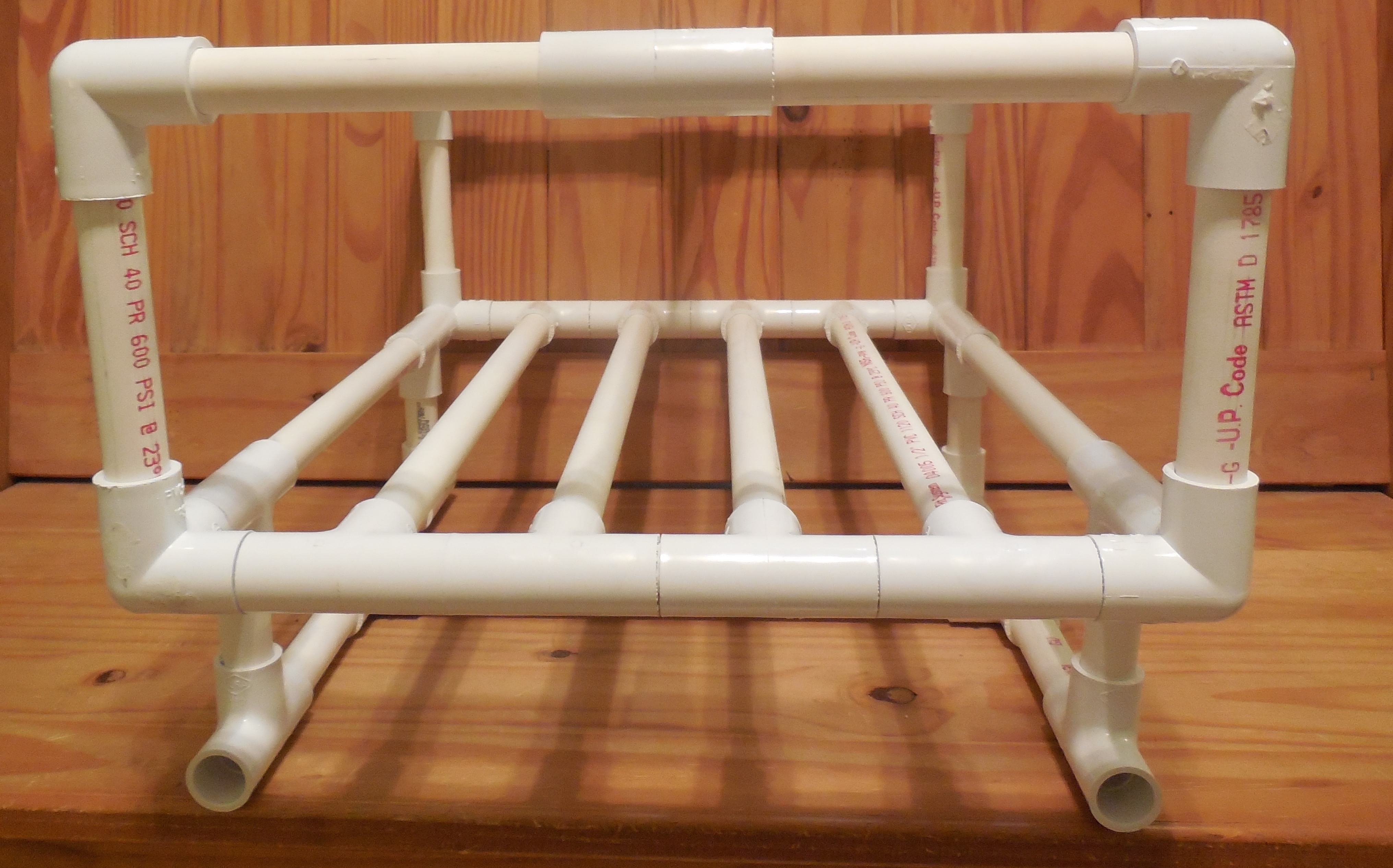
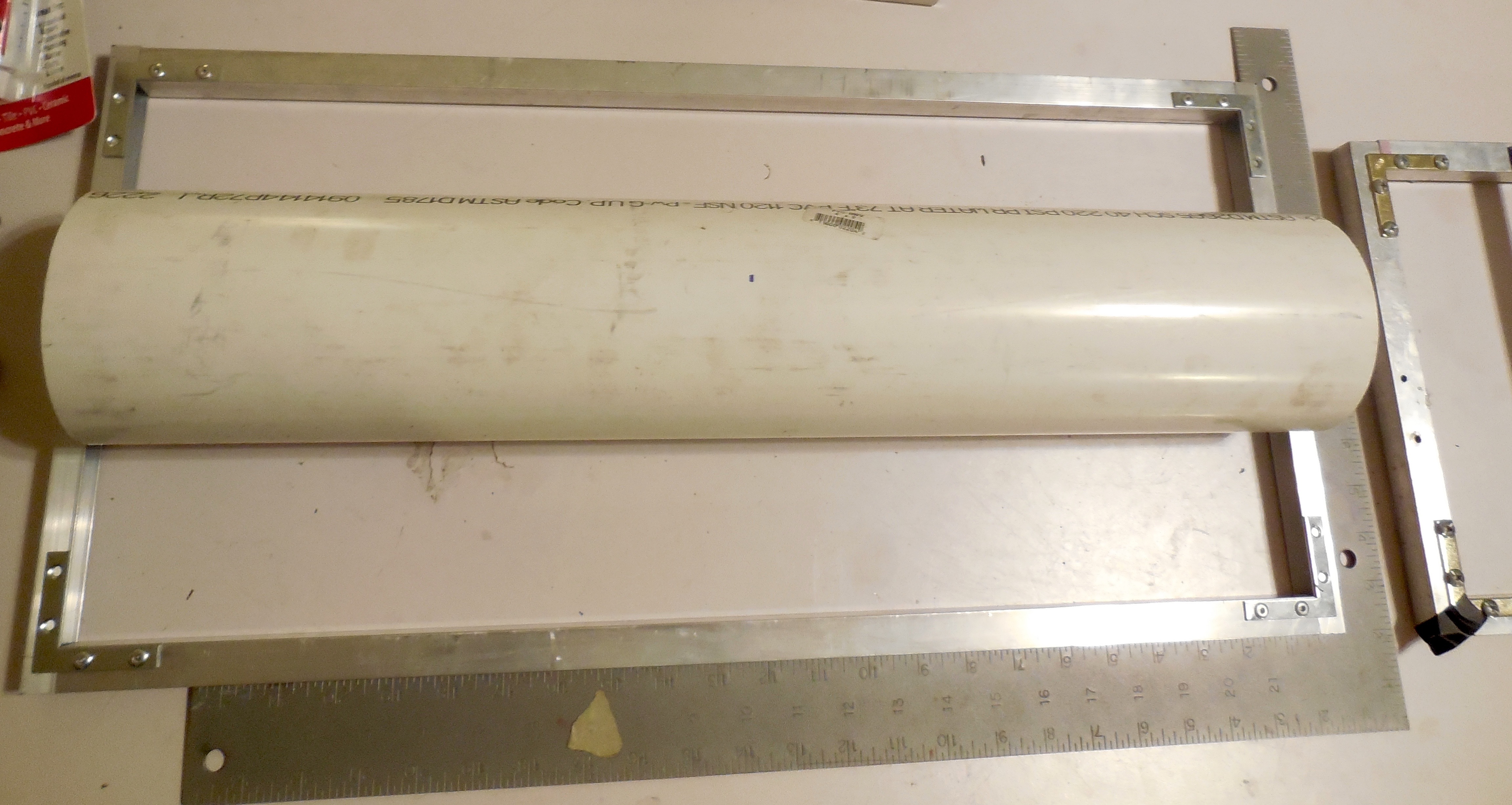
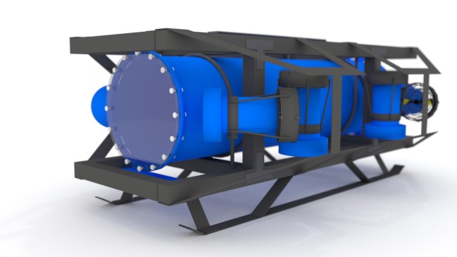
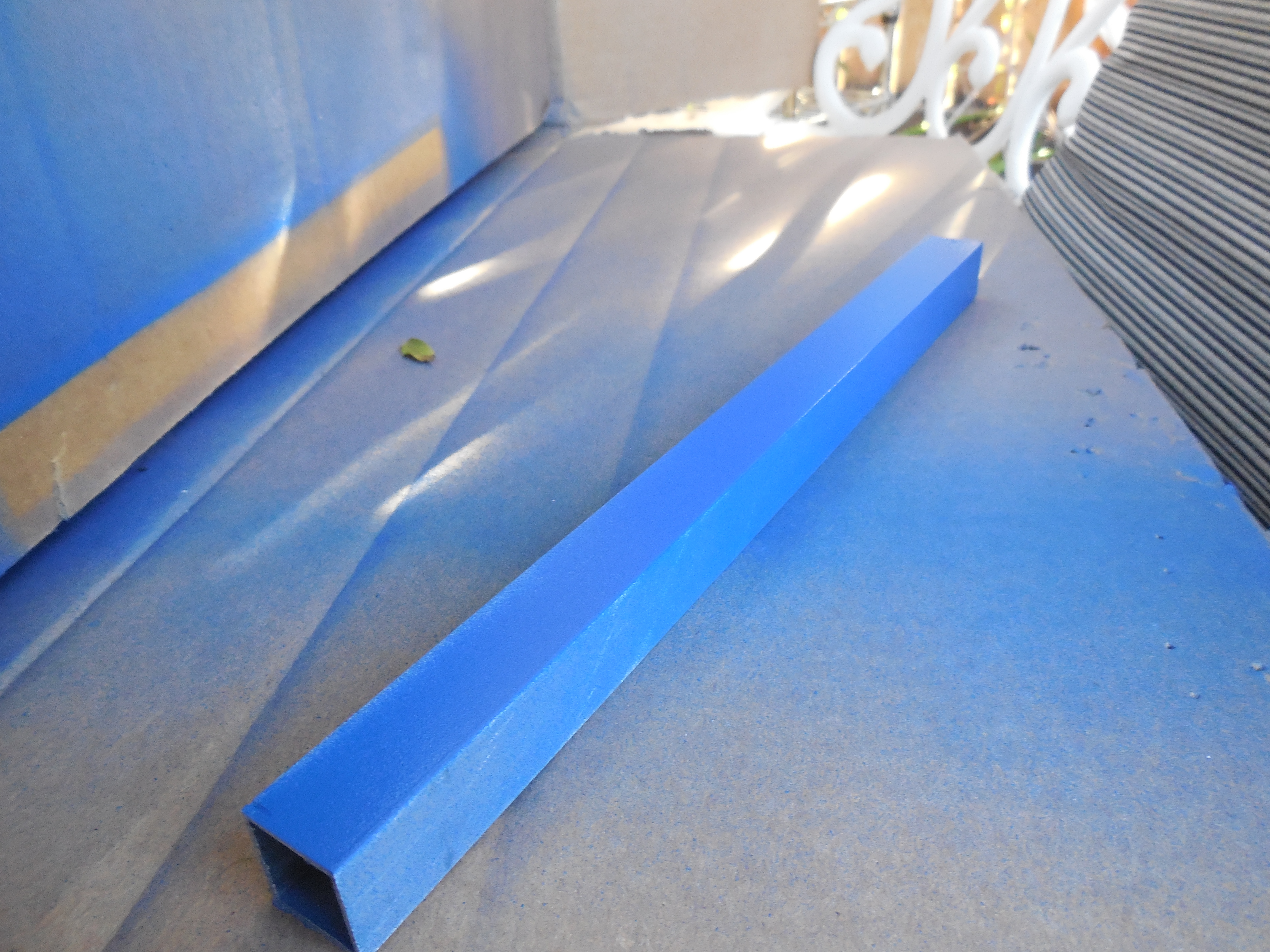
A major aspect of the rov has changed over the past couple of weeks. I wasn’t quite satisfied with Determination’s frame because there were some layout and access issues regarding the water tight containers. I contemplated just building a new PVC frame from scratch. Despite the extra time necessary I think building a frame specifically for these containers is the best option. I completed that new frame today, and while it ended up being a little bigger than I anticipated, I think it will work just fine. Due to the higher cost of aluminum this frame is made out of PVC, unlike my original design.

This main benefit of this new frame is that part of the electronics wiring will be simpler. With Determination’s frame whenever something in the water tight container needed to be serviced the tube would stay in place while the electronics sled would be fully removed. This meant that some sort of connector would be needed, as the wires from the rear end cap would have to be disconnected from the electronics. With this new frame design the acrylic tube and front end cap will pull away, leaving the electronics tray and rear end cap in place. This means that a connector isn’t needed between the end cap wiring and sled which greatly simplifies things.

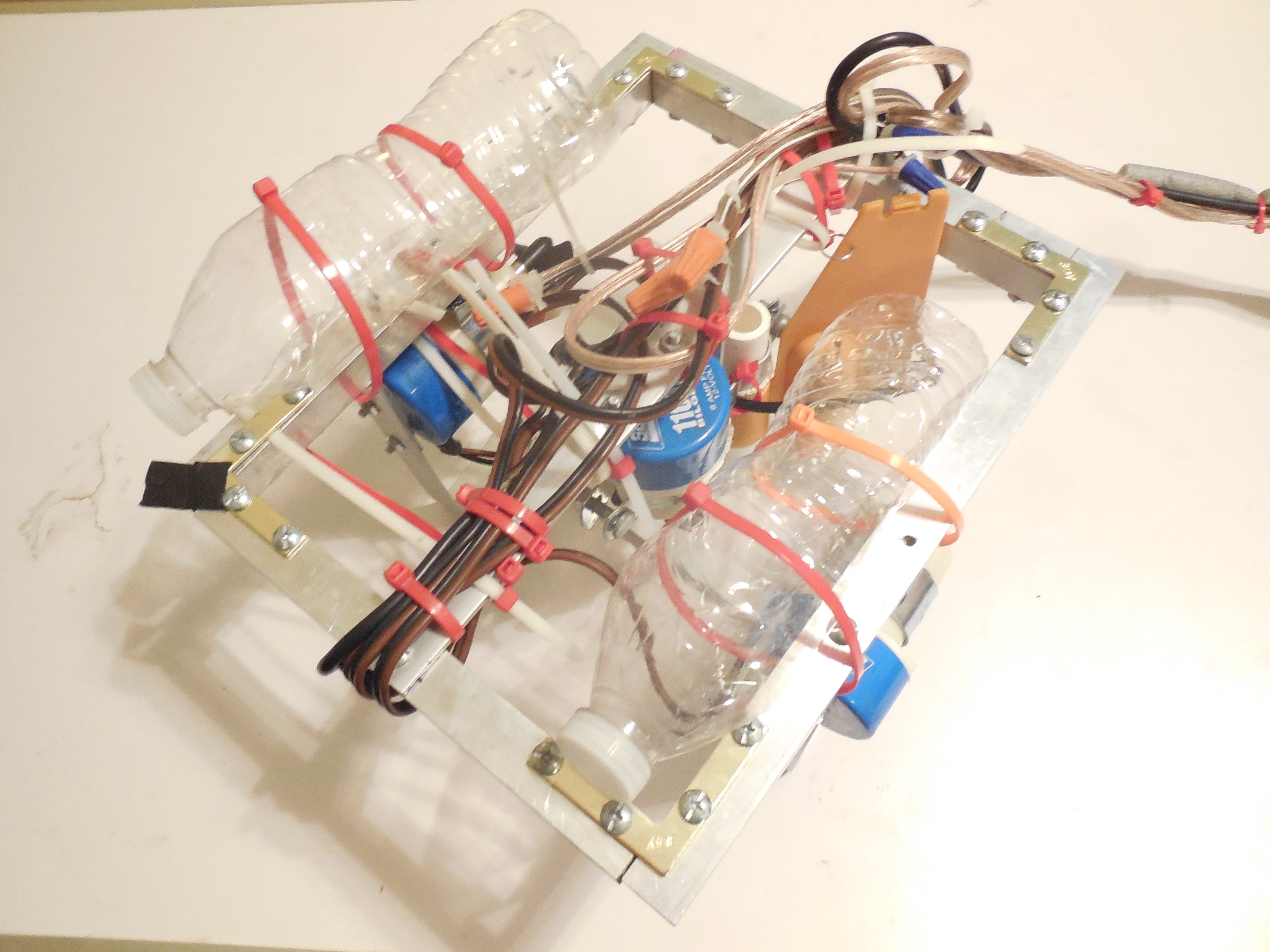
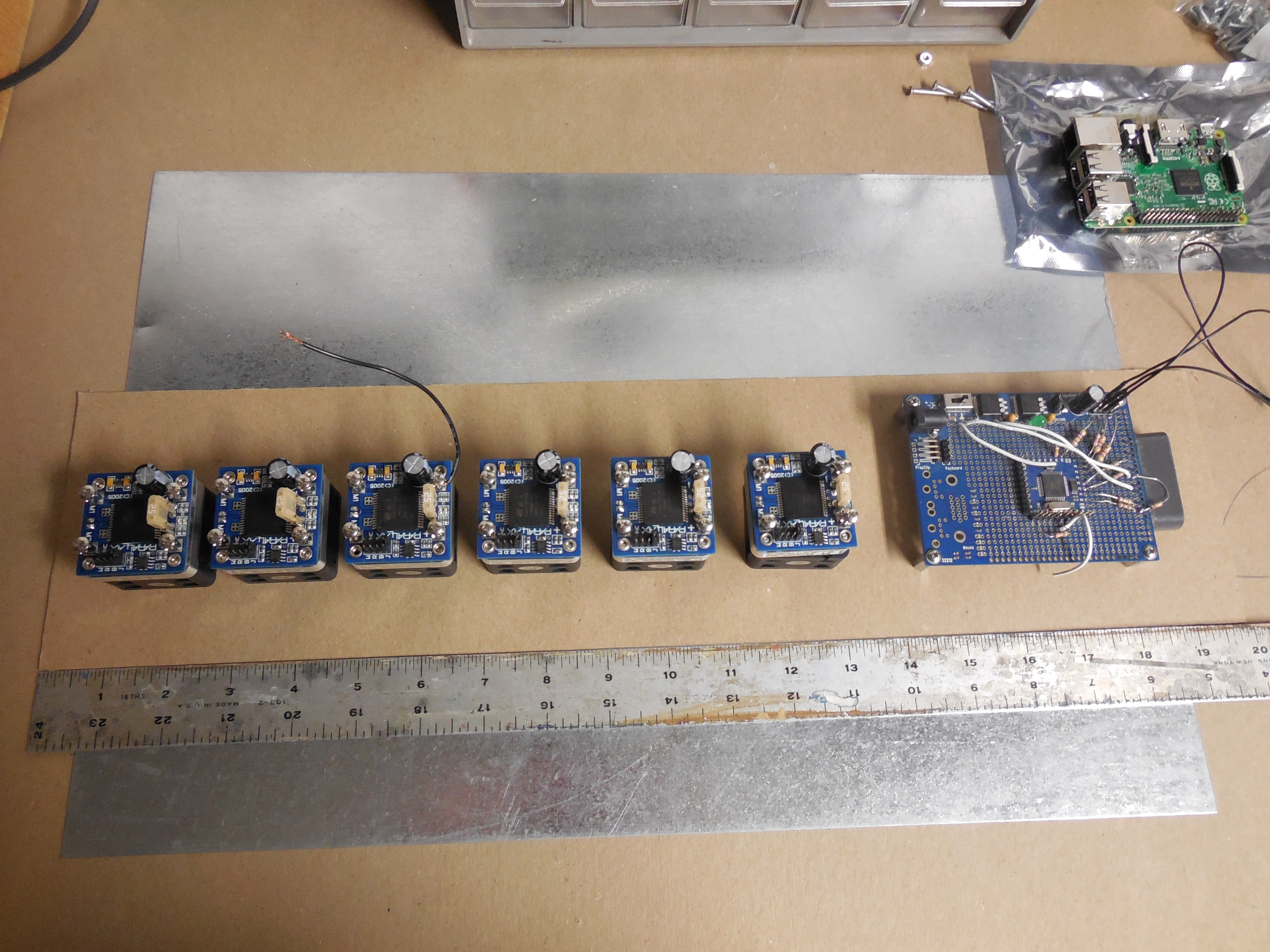
I also now have a solid idea of how the electronics will be located and secured in the containers. One container will be the “electronics tube” and the other will be the “battery tube”. The electronics container will house the Raspberry Pi, Propeller chip, four motor controllers, and some other components. The battery container will house a 3S 5200 mAh LiPo battery (perhaps two if necessary), a low-voltage alarm, fuse, two motor controllers, and probably voltage regulators for the lights, amongst other things. I’m not sure yet which container will house the tether communication system though. In each container a flat, horizontal piece of Lexan will hold everything in place.

Over the last couple of weeks I have also been working on the software. Nothing major yet, mostly planning, design, and writing some skeleton code. I have also been learning how to use Git and Github. Along with the software I have been focusing on the documentation, specifically what program and file-type will be used to create and publish the technical report and user guide. I am leaning toward markdown for the bulk of the report. Probably each section would have its own markdown file. As part of the publishing process a script could combine the markdown files together, convert that to pdf or odt  (possibly using Pandoc), and any other elements that markdown doesn’t support could then be added in (such as the parts list table). Since markdown is plaintext it will work will with Git and can be edited on any system using a simple text editor. The major downside is that markdown doesn’t support fancy layouts.

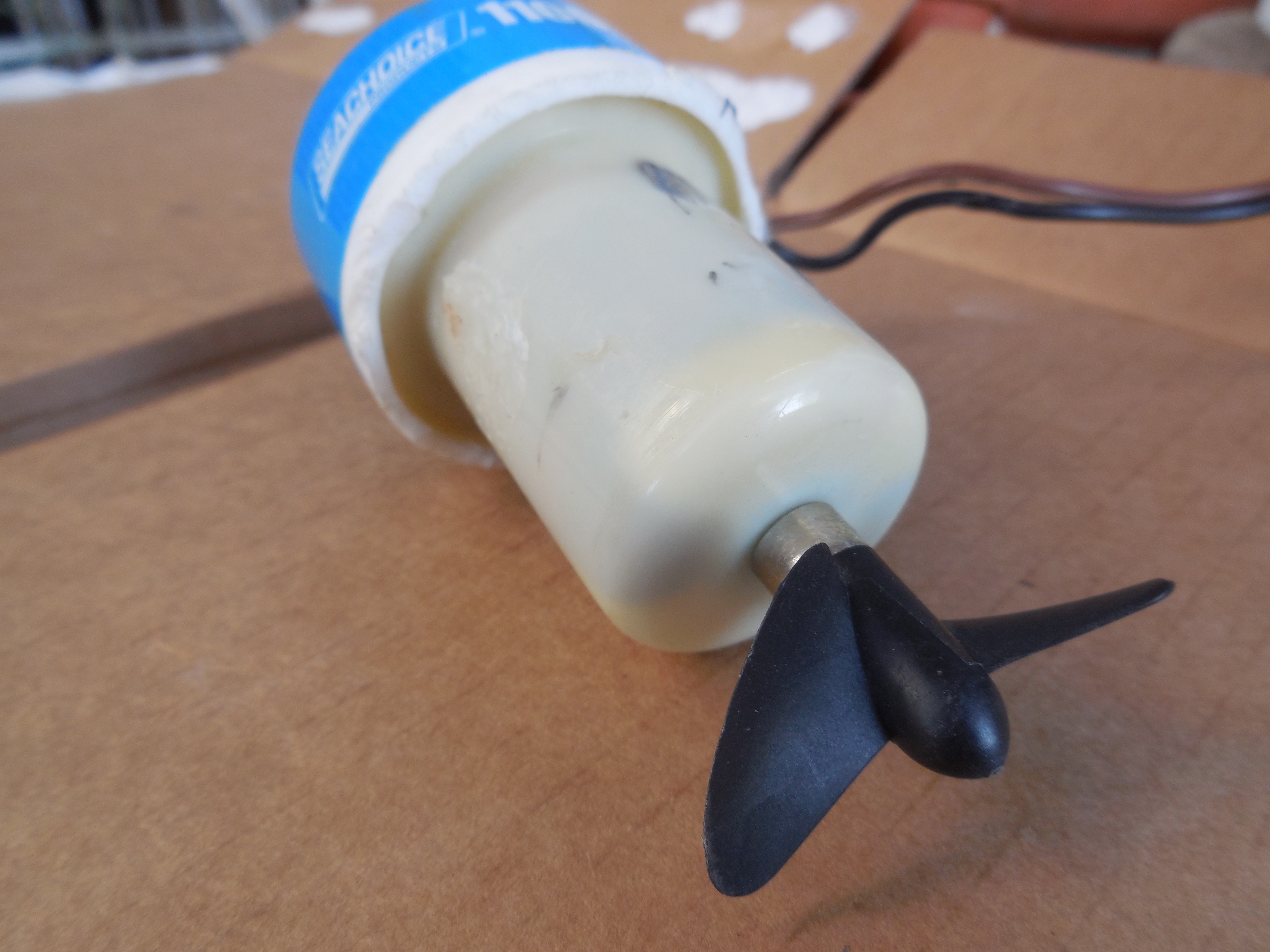
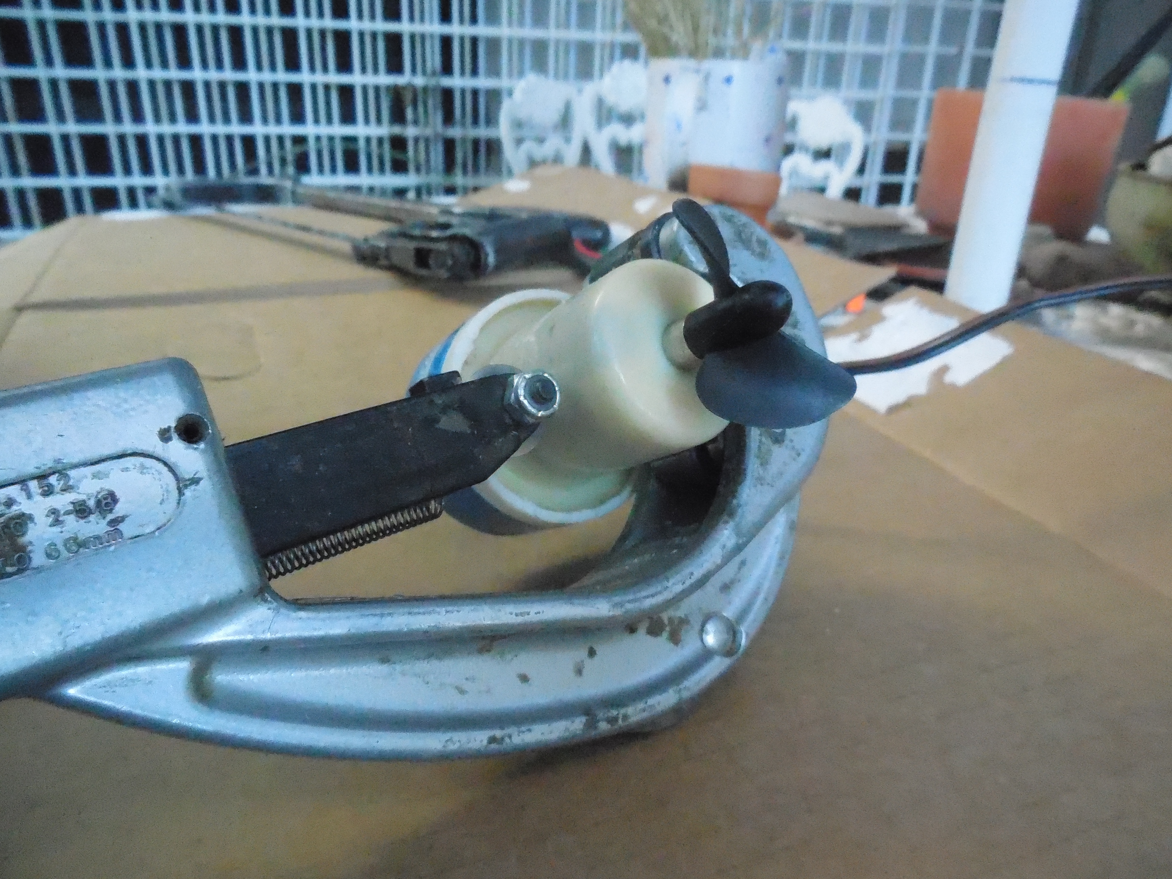
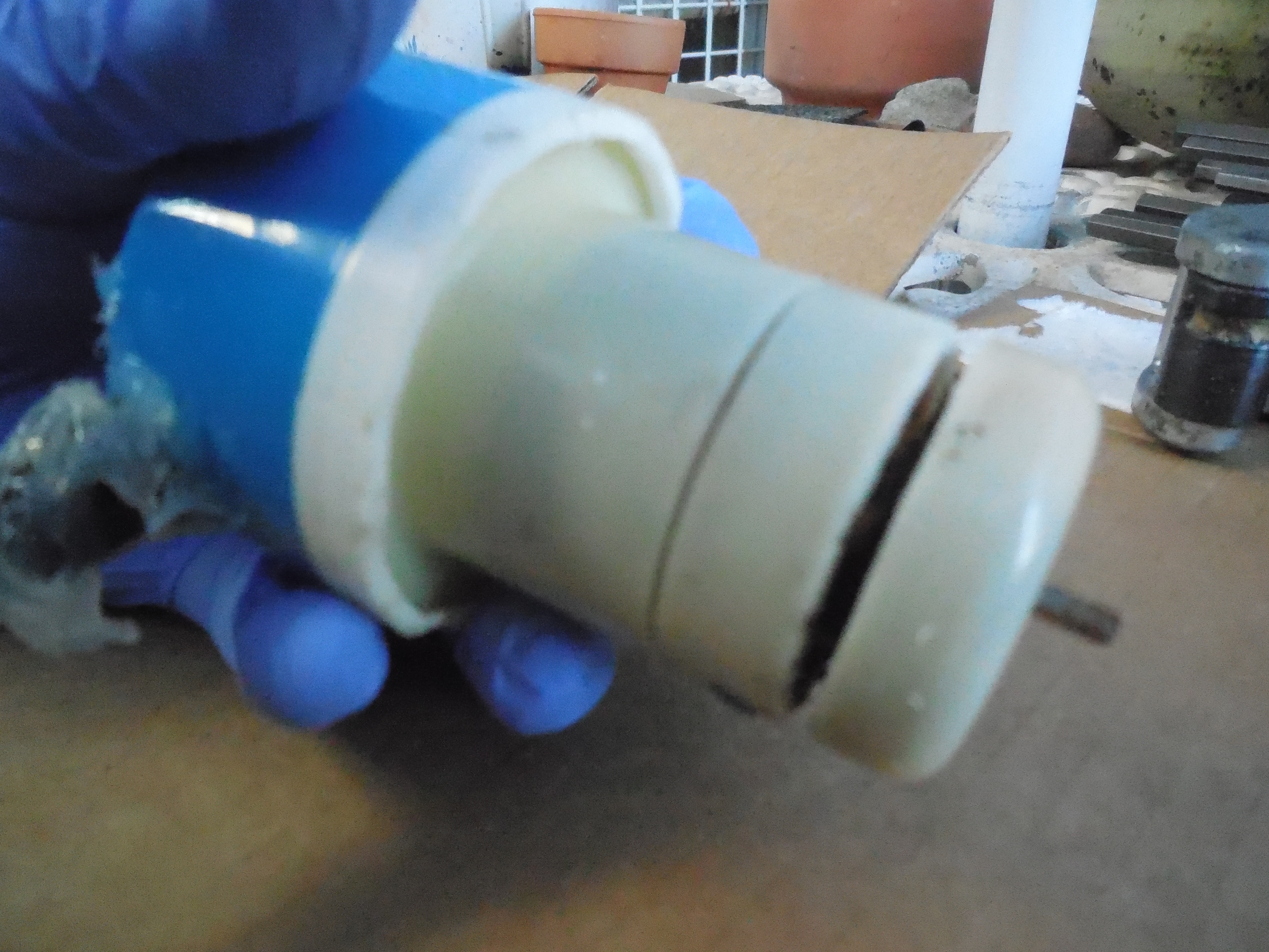
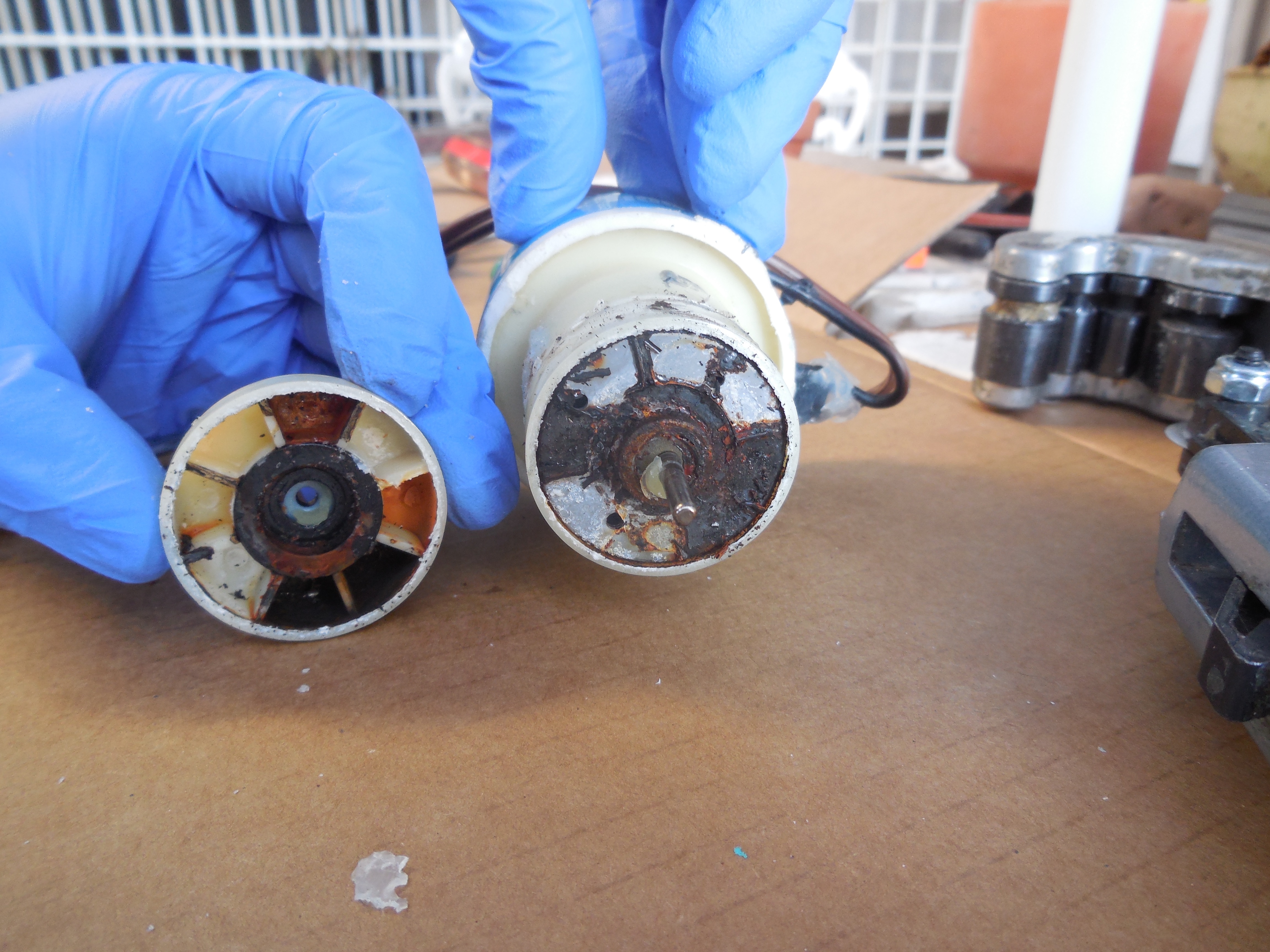
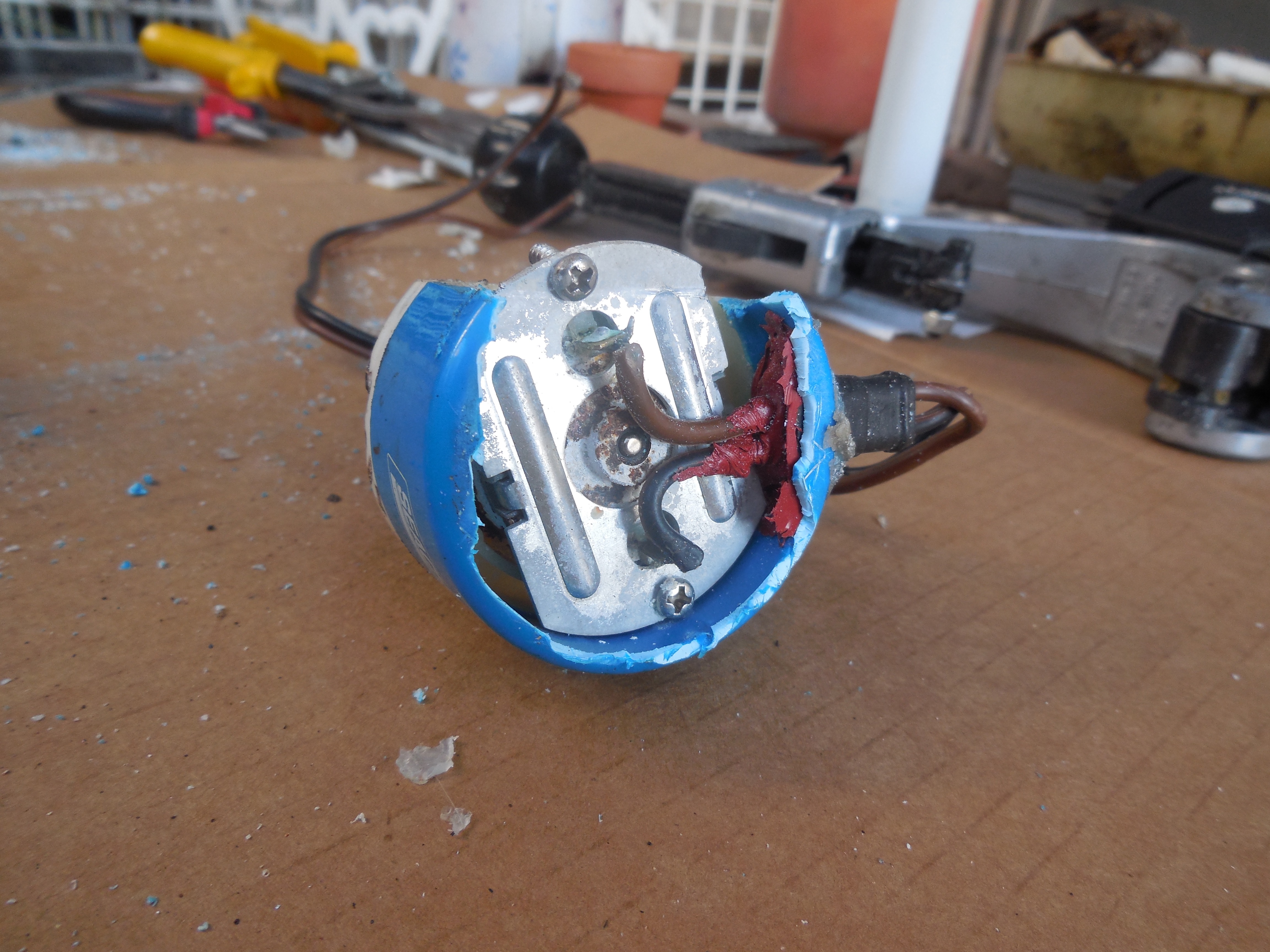
The first major setback occurred last week. It seems as though some water may have leaked into four of the thrusters I was planning on using. These motors are from a project from a few years ago. There is a grey discoloration on the inside of the motor housing. They all run, surprisingly, but they don’t sound very good. In fact, the shaft on one wouldn’t even turn a full revolution at first. I am going to take apart one of the damaged motors to get a better idea of what the problem is. Unfortunately all this means I will have to buy several more bilge pumps and convert them into thrusters.

KARR Build Log 10/7/15

Hull

I purchased a second watertight hull from Blue Robotics (same specs as the first hull) to house the batteries and any secondary electronics that don’t fit in the main hull. This means the rov will have two 4″x13″ watertight containers. While that is great for the electronics, it does complicate other aspects of the rov design.

Frame

Changing the design of the water tight container has complicated the current frame design. I had already built the major portion of the frame before switching containers, and the new design doesn’t really fit well with the frame. The new container is much shorter than the original custom hull I was going to build (13″ vs 24″). I tried different arrangements with the new containers on the frame and none of them are satisfactory. Ultimately the problem is that the frame is too long and since I riveted the pieces together it won’t be a trivial task shortening the frame. I pondered building a new frame better suited to the new containers. However, it turns out that the frame from a past rov I worked on is just the right size. That rov is Determination, an rov that I helped design and build while part of TCA Robotics. The frame from Determination is tall enough to stack two containers on top of each other, and just the right length and width. I probably won’t use Determination’s frame for KARR permanently, just for the time being so I can get the rest of the system up and running and figure out what to for the frame long-term. It is actually kind of interesting that I will be using Determination’s frame for this project, as I had designed a similar computerized control system for Determination, but we never got around to implementing it. I guess that will finally become a reality.

Software

Over the past week I have started designing the software portion of the project. I switched from Kivy to Tkinter for the operator console GUI framework. While Tkinter doesn’t seem to have as many features as Kivy, it does seem to be more straightforward in its usage. Assuming I can send a usb and composite video signal over the tether the GUI will be run on the Raspberry Pi. There will be two programs that form the overall GUI; a video player in the middle of the screen and the operator console GUI. The video player will probably be vlc or the built-in raspi camera preview program. Raspbian, the default operating system for the Raspberry Pi (based on Debian) uses LXDE for the desktop environment. Thankfully custom window rules can be set up in LXDE through a config file. This means that I can set up rules for the camera viewer window and the operator console. These rules include window size, position, keep above/below, whether the window has a title bar and border, etc. The camera viewer will be set to the screen center (x and y), no border or title bar, and “keep above”. The GUI will be set to maximize and no border or titlebar. I will probably write a bash script that launches the viewer and GUI at startup.

Thrusters

Today I figured out how to attach the propeller shrouds to the thruster mounts. I didn’t think there would be enough clearance between the propeller and bracket for this method to work, but thankfully there is, as this is a very simple way to attach the shroud. The thruster mount itself is actually made from two conduit hangers and a right-angle bracket. I have used this design on several other rovs and it has worked very well. A flat bracket joins the shroud to the rest of the mount. It is a ridiculously simple setup that hopefully works.

This slideshow requires JavaScript.

KARR Build Log 9/23/15

Over the past two weeks the research stage has been slowly transitioning into the build stage. I now have a better idea of how the system will function as a whole, though there are still many smaller details have have yet to be decided on.

Hull

I was originally going to try to build an aluminum waterproof hull for KARR, however I have been doubting how reliable that will be, given the techniques at my disposal. Fortunately I found a supplier of waterproof hull kits specifically designed for rovs. Blue Robotics is a fairly new company (started in 2014) that sells an assortment of ROV parts. Their selection is currently small, as they mainly sell thrusters and waterproof hull components, but hopefully it will expand in the future. They currently have two options for waterproof hulls: a 2″ diameter kit and a 4″ diameter kit. Each kit comes with an acrylic tube, two o-ring flanges with o-rings, two end-caps (they have several types to choose from) and a vent-plug. The components that come with the hull kit can also be purchased individually. Overall it looks like a very nice system. They also sell cable penetrators that can be used with the hull kit. With the kit, spare o-rings, cable penetrators,  and shipping the total cost came out to be $236, which is a bit pricey, though much better that several hundred dollars worth of water damaged electronics (assuming the hull-kit works properly and I don’t do something stupid).

Frame

I spent the evening today working on the frame. So far it is coming together nicely. The design has changed somewhat, though the overall shape is mostly the same. The upper layer is salvaged from a previous rov, while everything else is new.

Previous Rov
Previous Rov
Disassembled Rov
Disassembled Previous Rov

The top part of the frame along with the thrusters will be used for KARR. I also almost finished assembling the lower portion of the frame today; I am just waiting for some super-glue to dry so I can finish drilling out holes for the rivets.

Lower frame
Lower frame with 4″ x 12″ pvc pipe

Control System Refinement

Over the last couple of days I have been working on the control system design. Originally it was going to consist of three main elements: a laptop, Raspberry Pi, and Propeller Chip. The laptop would run the pilot console program (written in python). The pilot console would display the video feed along with sensor information and extra controls, such as motor trim sliders for example. A usb gamepad would act as the primary input for controlling the rov. The laptop would communicate with the RaspPi over ethernet or WiFi through the tether. The RaspPi would have a program that sends the video from the camera module over the network, along with a python program that would act as an intermediary between the laptop pilot console program and the Propeller Chip. The Propeller would be responsible for controlling the actual hardware and managing any sensors. Here is a “diagram” of the setup:

[Laptop]~~Tether~~[RaspPi]–[Propeller]–{Hardware}

After a bit of cogitation I settled on a different, more “compact” system. In this new layout the RaspPi is moved to to surface and integrated into the pilot console. Here is a “diagram”:

[Touch Screen]–[RaspPi]~~Tether~~[Propeller]–{Hardware}
[LCD TV]~~~~~Tether~~~~~[Underwater camera]

The pilot console will hopefully be a handheld unit that consists of two screens, a gamepad, and a compartment for the RaspPi and it’s battery. One screen will be a 7″ LCD TV, the other a 7″ RaspPi touchscreen (the “official” RaspPi touchscreen advertised on the RaspPi website). The LCD TV will display the rov’s video feed, while the touchscreen will display the pilot console program. I’m not quite sure yet what method I will use to transfer data over the tether. I have a few ideas, but will save that for a later post. The camera will be an off-the-shelf underwater fish cam from ebay. I have used these in previous projects and they seem to work decently well.

So, what are the benefits of this revised system? Well, it provides two main benefits.

  1. It makes my life a little easier (hopefully). In the original system the python program was essentially broken up between two devices. This meant that I would have the additional overhead of getting the two parts reliably communicating over tcp or udp. While that’s not an impossible task, it adds additional complexity which not only takes more time to develop, debug, and maintain, but also adds a major failure point. With this new design those the parts are consolidated into one program.

  2. It simplifies the user experience. The end user doesn’t have to worry about installing a pilot console program on their laptop and trying to get it to communicate with the rov’s internal computer. The pilot console is now one device that is preinstalled with the appropriate software. All the user has to do is connect it to the tether and power the rov and pilot console on. No dealing with weird issues caused by the myriad of variables that are present with a “bring your own laptop” scheme.

KARR Build Log 9/8/15

These first two weeks have primarily been sourcing parts and refining ideas. So far I have most of the major electronic components and an assortment of mechanical parts. All of the HB-25 motor controllers from Parallax have arrived, along with a Raspberry Pi 2 and inertial measurement sensor from Adafruit. I also have an assortment of aluminum for the frame and Lexan for various assemblies. I have six thrusters left over from previous projects and three un-modified bilge pumps. While I still need to build shrouds for all eight thrusters, at least I have a pretty good idea of how they will be constructed.

Labor Day provided a great opportunity to start working on the ROV. I spent a couple of hours tidying up the workshop and then got to work. I started the day out by painting some aluminum. It’s just a short piece of scrap to test how well the spray paint looks and adheres. I chose a slightly dark blue for the hull and thrusters and a dark grey for the frame.

Paint test
Paint test
Internal Layout Idea
Internal layout idea

Next I cut out a 20″ x 4.75″ piece of thin cardboard to serve as a guide for laying out the internal components. The hull that the electronics will go in is 5″ in diameter by 24″ long. The wall thickness will hopefully be 1/8″ thick. This means the usable diameter is 4.75″ or so.

Hull outline
Hull outline

I also drew a circle on my workbench so I could see if the components, especially the HB-25s would fit. So far everything seems like it will, though it may be tight. It is important to note that the batteries will not be going in the main hull. I will either route power thru the tether or use a separate waterproof compartment on the rov to house the batteries.

To reduce the height of the motor drivers I am planning on removing their fans. Of course, when modifying the thermal management portion of a device one must be careful that the device doesn’t overheat. A poor thermal design could end up damaging the motor drivers. Since I don’t know how much heat one of these will produce under load, I decided to do a simple test to get a rough idea how the driver will perform under minimum load. I removed the fan from one of the HB-25s and connected it up to two bilge pumps in parallel. This is similar to the setup on the finished rov. Fortunately the HB-25’s heat sink did not feel noticeably warm (which is what I expected). At a later time I will test the drivers with more load and for a longer period of time, and see how much heat is generated (in addition to more detailed values, i.e. voltage and current within the system). The plan is to put the HB-25s in their own watertight container filled with mineral oil. This will help protect them in case water were to leak into the hull and hopefully help draw heat away from the drivers.

Now that I have a fairly good idea of how the electronics will be arranged inside the hull I can go ahead and purchase some aluminum tube. Over the next couple of weeks I will focus on assembling the electronics so I can begin writing software and building the frame and thrusters.