Urban Monstrosity was my first foray into underwater robotics and was the first robot built by TCA Robotics.
 Since our experience with ROVs was very limited and our budget was small Urban Monstrosity was built with inexpensive, off-the-shelf parts. Developing Urban Monstrosity was a constant learning experience; we found out what works well for an ROV and what works not so well (mostly what works not so well). Below you will find information from the tech report, which can be found here.
Table of Contents
Abstract
The Team
Frame
Motors
Lights
Camera
Laser
Manipulator
Pilot Controls
Tether
ROV Electronics
Buoyancy Testing
Educational Impact
Record of Purchases
References
Acknowledgements
Abstract
This project is the result of unfailing perseverance and motivation. The venture started
with no funding and no experience. Several times during development, team members
felt like quitting and giving up. It seemed that financing and other limitations hampered
every aspect of planning and construction. The goal of building an underwater robot
seemed impossible. However, a bond of friendship combined with a sense of
commitment pushed the endeavor to completion.
The focus has been on fulfilling the mission requirements in both affordable and novel
ways. The results are readily apparent. The team’s robot is built from a mixture of
recycled materials and common objects. The robot is an original combination of ideas
and designs along with an amalgamation of PVC and metal. As a result, the robot, aptly
named Urban Monstrosity, looks unpolished. However, appearances are deceiving.
Underneath the roughness is the ability to succeed.
The Team
Kristian Charboneau originally proposed the idea of a robotics team to the
administration of the school. He had watched the NURC competition for many years
and was very interested in starting a team. After bringing the idea to the
administration, he was pleased to find the school’s enthusiasm. Almost immediately,
a sign-up sheet was put up and a team was “assembled”. Aside from being the key
organizer for TCA ROBOTICS, Kristian served as one of our team leaders. He
guided the work of the rest of the team in making sure that the goals for each day
were accomplished. Also, Kristian was our electronics expert, and he headed up
programming all of the electronic components and making they worked together
seamlessly. 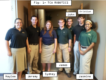
James Reynolds was attending Tri City Christian Academy for his senior
year (their family had recently moved to the USA from Singapore and was eager to
get involved in extra-curricular activities. He was pleased when the signup sheet for
robotics went up. A lover of science and engineering, robotics was the perfect fit.
James served as our other team leader. Working in collaboration with Kristian, he
helped make sure that the whole team was focused on the goals at hand. James was
instrumental in getting the website up and being the main hands-on guy in the
construction of our frame. Unfortunately, due to his family’s move to North
Carolina, James will be unable to participate in the actual NURC competition.
Sydney Trogen had worked with Kristian on science projects in the past. It
was in their seventh grade year that they won the state wide Aerospace Challenge,
winning a trip to Houston. After that amazing experience, she knew how much fun
those kinds of science projects could be. Also being intrigued by the concept of
robotics, she decided to join the team. Sydney helped out however she could, and
worked the most on the Lights. Sydney’s father, an engineer with Boeing, also
helped us with the construction of our ROV. Unfortunately, Sydney will not be able
to attend the competition because of a trip that had been planned prior to joining the
robotics team.
Jeremy Tetreau had worked with both Kristian and Sydney on the Aerospace
Team the year before the TCA team won. So, like Sydney, he had some background
in science projects. Jeremy joined the team not knowing what he could do. In the
end, that was what was most helpful. Jeremy worked wherever he was needed,
drilling holes or gluing a piece of PVC. However, he was most instrumental in
creating the team YouTube video, as well as working in collaboration with James on
the final draft of the Tech Report.
Jasmine Davis came onto the robotics team excited for the opportunity, she
thought that the idea of building a robot from the ground up was amazing, and so she
actively participated. Jasmine helped wherever she was needed, but was most helpful
on the robotic claw. She helped take the concept and turn it into a reality. Jasmine
also served as the photographer of our team. At every meeting she was always taking
pictures, to make sure we didn’t miss anything!
Haylee Garcia was excited to join the team. Though she had never done
anything like it before, she was ready and willing to do whatever was needed of her.
She helped out with making sure there were always sets of screws and bolts to use,
and helped Jasmine with the robotic claw. Along with those specific things, Haylee
helped out whenever and wherever she was needed.
John Reynolds, the younger brother of James, came on to the team with
excitement. Always full of lots of ideas, John was very helpful in the planning
stages of the project. Along with that, John was most influential on the light
systems, along with sanding the edges of anything was cut, to make sure we had
clean, smooth pieces, to the best of our ability. Aside from those things, John also
helped cut the studs and doing whatever else was needed. John and his family
moved to North Carolina, so he will be unable to attend the competition.
Every one of the team members gave up many hours of their time, devoted
themselves to the work that needed to be done, and did what the team leaders asked
of them.
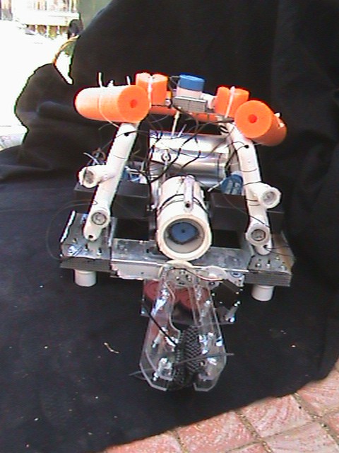
Frame
The primary function of our frame design is to insure that there is sufficient space
for all of our necessary components. It is essential to place the “internal organs” of the
ROV where they can best do their job and work together with the other components. It is
for this reason that we chose a trapezoidal prism. We constructed the bottom rectangle and the top cross beam out of flat metal studs, rather than PVC, to allow for easy
bolting on of different components. With PVC, it would be difficult to bolt everything
together and still retain confidence in the ROV’s structural integrity. However, the “slant
height” of our trapezoid was constructed out of PVC pipe.
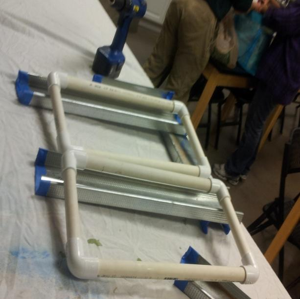
Fastened to the bottom rectangle using pipe clamps, the PVC section allowed us to very easily set the exact angle that was needed to support the upper cross
beam. In addition, our LED lighting could easily be attached to extensions of the PVC.
Along the PVC pipes are holes to allow for water to flow in and out. When our ROV is in
the water, the water fills the pipes and helps maintain a proper center of buoyancy. The
water is also allowed to drain out of the pipes after the ROV is retrieved. To help with
buoyancy, we cut pieces of pool noodles and attached them to the outside of our frame.
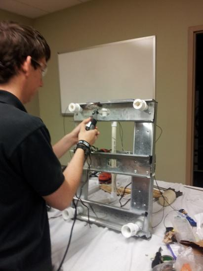
To protect the robotic claw, small PVC “feet” were positioned to keep the claw from colliding with the pool bottom. Although implemented as a safety measure, it aided us in the construction of our ROV. We could thread wires and attach things without having to continually rotate our robot around.
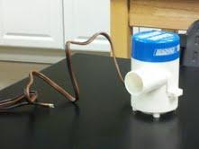
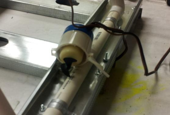
Motors
When we began constructing our ROV, little did we know the cost of some
underwater motors! Balancing our financial limitation with our proposed requirements,
we decided to purchase bilge pump replacement cartridges and modify them.
The bilge pumps each had an impeller and casing to direct water. We really only needed
a waterproof motor. To prepare the pumps, we took turns, as with most of our projects,
cutting off the original tubing using a pipe cutter and a hacksaw. After the thin
plastic inlet, we plugged up the outlet with a wooden cork. Then we sealed it with
silicone glue and attached a propeller to the shaft inside the housing.
We placed two of the newly modified pumps symmetrically in the middle of the
two side beams. They function as our horizontal motors moving the ROV forwards and
backwards. Another motor was placed in the center of the upper crossbeam. It functions
as the vertical motor and propels the robot up and down. The final motor was placed on
the lower crossbeam in the center of the frame. It is our lateral motor and pushes the
ROV from side to side. Although they may not be an incredibly powerful array of
motors, they do provide sufficient force to maneuver our ROV.

Lights
Keeping the theme of inexpensive functionality, we decided to make use of small
inexpensive LED flashlights. The LED flashlights’ metal shells were cut open to
allow the actual LED component to be isolated for modification. Wires then were
soldered onto the LED circuit boards. This allowed us to position the lights without
being concerned about the location relative to the power source. The newly soldered
LED components were then secured inside a threaded PVC reducer. The small opening
of the threaded reducer was then sealed using a silicone-based glue.
The wide front opening, containing the front side of the LED component, was covered by a Lexan
circular lens and also sealed using the silicone glue.
The newly created LED headlight was screwed into a PVC threaded T, which
was placed on the PVC diagonal frame piece. Holes were drilled in the original
PVC to run the wires through the frame to the microcontroller box, which is
subsequently connected to the power source.
Camera
 Cameras come in all shapes, sizes, and prices. We wanted to purchase a
waterproof camera with a decent picture quality. Unfortunately, finding such a high quality waterproof camera on an extremely low budget is nearly impossible. As with many other components on our ROV, we had to go with functionality as opposed to the highest quality. One of our team members (Kristian Charboneau) had a security camera that he was willing to use for our ROV. However, the camera was not
waterproof. The solution was a PVC pipe casing.
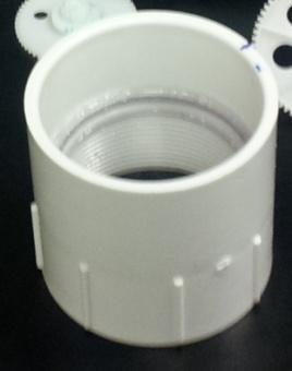
A PVC pipe, 7.62 cm (3 inches) in diameter, was cut to a length of 20.32 cm (8 inches). The ends were smoothed off using a thick grade of sandpaper. Then two threaded couplers were mounted on the ends and secured using thick glue. The next
step was mounting a clear lens for the camera to see through. A circular piece of Lexan (a clear polycarbonate resin thermoplastic) was cut to a diameter of 7.62 cm (3 in.), and was glued to the inside of the front coupler, which left about an inch of thread. The threaded section was cut off to allow the camera a full peripheral view, unobscured
by the PVC. To carry the video and power lines, a small hole was drilled in the back of the ABS cap. A 0.95 cm (3/8-inch) diameter air hose was then inserted into the hole
and sealed using a silicone-based glue. After the hose was sealed and the necessary
wires secured, the ABS cap was screwed on to the back coupler along with thread tape
to insure a secure seal.
Attaching the camera casing to the frame was accomplished using an 8.89 cm (3.5-
inch) U-bolt. Holes were drilled in the center of the lower front crossbeam where the U-
bolt was fastened on. A rectangular Lexan piece also supports the back end of the
camera housing.
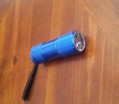
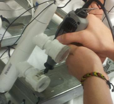
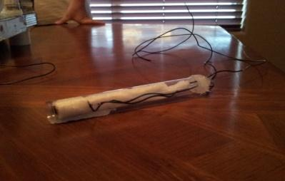
Laser
An inexpensive keychain laser pointer [Fig 13] was purchased for our ROV. As
with the flashlights, we began our modifications by cutting open the metal shell. After
the shell was cracked open, the internal components were removed for individualized
modification. Wires were then soldered on to the battery terminals. As soon as the
wires were securely attached, the entire module was wrapped in electrical tape. The
reconstructed component was then wrapped with white foam packing sheets to secure it
inside the clear plastic cylindrical tube it was placed into [Fig 14]. A small hole was
drilled in the back of the tube to allow the wires to connect to the microcontroller box.
Finally, the end cap was sealed using a silicone-based glue.

Manipulator
As with the rest of our ROV, the budget won the contest for the design of the
claw. We had Lexan readily available for use, so the arms were cut out of a flat piece.
To ensure the stability of the arms, two arms were cut and then held together by spacers
and bolts, all of which function as a single arm. At the end of the doubled arm segment,
rubber grips, as are seen used in kitchen cabinets, were zip tied to fill the open space.
The single arms, consisting of 4 individually cut arm pieces, were then placed
on top of two vex gears, which move according to the movement of the servo motor.
The motion of the arms begins when the servo, which is controlled by the
microcontroller, rotates the smallest vex gear. When the smallest vex gear rotates, the
arms attached to the two equally sized vex gears rotate in opposite directions, causing
the arms to “grip” an object.
The above paragraph is a description of the “gripper” motion. However, our claw is
also capable of rotational movement. This is achieved through another servo, which is
attached to another gear. When this gear is turned by the servo, a larger gear, which is
attached to the entire claw component, rotates the claw.
The claw is located in the center of the front lower crossbeam, directly in front of the
camera. This allows for the missions of the claw to be observed using the same
camera as our general sight, which was the best solution for a seemingly high-priced
task.
Pilot Controls
A pencil box to houses the pilot controls. Being easy to cut and a perfect fit for
the electronics, it was cheap and ideal for housing the controls. The central component
is a Parallax Propeller microcontroller. The microcontroller was chosen for its speed
and parallel processing capabilities. In addition, some members of the team have had
past experience with it. A Playstation 2 controller [Fig 18] is used to control the ROV.
With its intuitive use as well as its ease of hardware and software connectivity to the
microcontroller, the Playstation controller worked well as a low cost option. Only four
resistors were needed and the core driver was obtained from the Parallax object
exchange. However, we did need to write a more intuitive interface for the driver. The
console microcontroller communicates with the ROV microcontroller over the CAT 5e
tether cable. A toggle switch controls the on/off relay in the ROV. The camera feed is
displayed to the operator by a 7 inch LCD TV.
Tether
The tether consists of a 30.48m CAT 5e cable and rope for added strength. Four
lines are used for communication between the two microcontrollers. Two are used for
the video feed. The other two are used to power the ROV’s on/off relay.
ROV Electronics
A Propeller microcontroller [Fig 19] acts as the brain of the ROV. It controls the
motors, servos, lights, and the laser. The Propeller’s multi-core architecture was very
useful in the software design process. Tasks that required a lot of resources, such as
PWM and servo drivers, are assigned their own core; this allows for quick and smooth
flow. We are using Infineon TLE5205 motor drivers, which provide ample voltage and
current ratings while being easy to use. The only external component needed is a 100
uF capacitor, as the chips contain built in diodes for driving inductive loads. The lights
are controlled by a small relay, driven by an nte123ap signal transistor. The laser diode
is turned on by another nte123ap signal transistor.
Buoyancy Testing
After 2 months of construction, we were finally threw our ROV into the pool
to tackle the buoyancy issue. Buoyancy was an issue was because of the changing
inventory of equipment. Our original plans were to use PVC tubes filled with air as
ballast for our 15 pound underwater “brick”. However, even with donated piping, such
a system would be too expensive. The team did have pool noodles that would float the
robot. The disadvantage to using pool noodles was their unknown density. Using PVC,
the buoyancy force could be calculated. The pool noodles could only be approximated.
Therefore, we had to use trial and error (as recorded below) to find the required
amount to achieve a neutral buoyancy.
What we discovered was contrary to our first guess. Instead of sinking to the
bottom, the two pool noodles actually kept our “brick” on the surface of the water!
We, however, still needed to reach neutral buoyancy. For the next drop we removed
one of the pool noodles. Unlike the first drop, the back end of our ROV sank [Fig.20],
because of the added weight of our heavy battery (represented by an 8- pound
dumbbell for this test). In an attempt to correct this, we cut off 5.08 cm (2 inches) of
pool noodle on each end to balance both sides. To our surprise, even these small
sections made an impact on our buoyancy. When we did the third drop, we watched as
our ROV began to sink to the bottom. Apparently, we had taken too much off. We
then symmetrically zip tied the 5.08 cm (2 inch) sections that we had cut off to the top
center cross beam on either side of the vertical motor. When we put our robot in the
water for the 4th drop it sank and then floated up towards the top when we pushed it
[Fig. 21]. After a couple minutes it sank very slowly to the bottom. This was right
where we wanted to be. We have a system that has almost neutral buoyancy. As soon
as the ROV was completely constructed, a second buoyancy test was conducted to fine
tune our ROV’s performance including adjusting the motors for better performance.
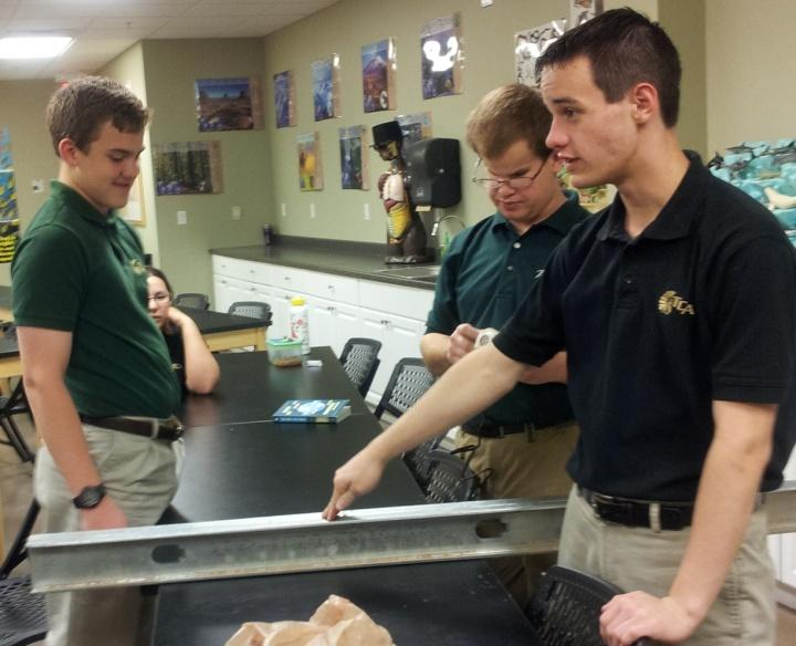
Educational Impact
From the very beginning of this entire process, we all knew that it would be a
long journey. Only two of our team members really knew what they were doing. The
rest of the team was made up of students ready and willing to learn. The result was a
long journey full of training. For starters, many of us learned how to use a drill. As
funny as that may sound, it is true. We all took turns drilling different things. Now, we
are all semi-proficient. The entire project, including this paper, was the first time that a
collaborative enterprise like this was ever embarked upon by many of the team
members. We learned how to write, plan, and communicate. Beyond the skills that
were learned, the entire process in which the final ROV was constructed taught us that
despite our best attempts at planning, we always needed to be flexible. A perfect
example of this concept is in our overall frame design.
In the beginning stages of the project, our idea of a frame was centered on a
VHS player [Fig. 22]. The idea was to take a VHS player and “gut” it. We would then
use the surfaces, inside and out, to hold the necessary components of our ROV. After
looking for the perfectly sized VHS player and not finding anything, we started to
reconsider.
One day during our weekly lunch meeting (our main planning sessions), the
head maintenance director at our school gave us a tour through the “junk yard” and
showed us which things we could use for our project. It was there that we first saw the
metal studs. We picked out several and started to brain storm ways to use them. It was
then that we thought of the trapezoidal design, to increase stability, and to utilize the
metal studs. From there our design began to evolve until the final design was settled.
Looking back at this whole project, there were things that made us laugh, and
enlightened us in the process. The constant dragging of our tools and materials back
and forth was one such situation. For the entire first block of construction, the
materials and tools we needed were dragged from Mrs. Charboneau’s (Kristian’s mom) trunk, through the parking lot, up the elevator, and into the science lab. About
half way through, when the trips were getting ridiculous, we thought, “There has to
be a better way.” It was then, only then, that we discovered the storage closet. In the
science lab is a large storage closet used to store extra books for the school, TVs, etc.
So for the second half, our trips from Mrs. Charboneau’s trunk were much easier
because our tools and materials were left in the storage closet for the next meeting!
Though it’s a funny moment in our journey, it illustrates our entire philosophy as a
team. Our entire project was based off of our budget. Because of this, we were not
completely sure of its functionality. However, whenever something happened
contrary to our original intent, instead of giving up, a solution was found. Things like
where we stored our project came to express who we are as a team.
We’ve learned how to work as a team, allow our thoughts and designs to
evolve, and develop solutions to seemingly difficult problems. One aspect of learning
that is irreplaceable, however, is failing. Learning from your mistakes is a principle
that not only applies to this project but to life in general. Our electronic system was
part of the process. As we were doing the electrical work, we burned out one of our
H-bridges [Fig 23]. The entire propulsion electronics system had to be redesigned.
This took up limited time and energy.
Another aspect of our learning was letting the testing prove us wrong. The
most dramatic example of this was the first buoyancy test. By the time we were ready
to test our buoyancy, every one of us thought that it would sink to the bottom of the
pool, even with the two pool noodles attached [Fig. 24]. However, to our great
surprise, it floated! That’s the cool thing about science: you can be wrong and still
learn what you need!
Record of Purchases
References
- Robot Magazine- September 2011
- Parallax.com
- Digikey.com
- Infineon
Acknowledgements
Financial Support
Kaiser Aluminum
Mr. Greg Leake
Mr. Bill Alkema
Chuck and Janet Hart
Tri City Christian Academy
Other
Mr. Ken Trogen- Assistance/ Tools
Mr. Deryl Degraw- Use of Science Lab
Mr. Steve Charboneau- Tools and Materials
Mr. Roman Ebert- Technical help/Donated parts
